 |  |  |  |  |  |
|---|---|---|---|---|---|
 |  |  |  |  |  |
 |  |  |  |  |  |
 |  |  |  |  |  |
 |  |  |  |  |  |
 |  |  |  |  |  |
 |  |
Click on a picture in the gallery above to see a full resolution image, or to navigate manually
Panavia Tornado GR1
No. 9 Squadron
Tabuk, Saudi Arabia, 1991
Why this plane?
I think there was something inherent to the engineering involved in creating variable geometry wings that resulted in some of the most beautiful planes ever built. After building the Tomcat, the Tornado became the next (but hopefully not the last) swing-wing jet in my collection. I love the look of this plane.
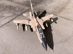
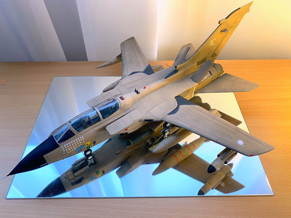
Among the many options provided for in the Italeri kit, I chose to build "Armoured Charmer" one of the planes deployed by the RAF during Operation Granby. The striking combination of desert pink camouflage, severe weathering, and wild nose art makes these RAF Gulf War Tornados scale modelling gold.
What was added
-
There were no aftermarket items; built out of the box, with a few "upgrades" made from items I had around the house and garage.
-
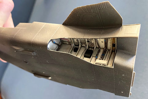
One of the upgrades was to the undercarriage bays, which were pretty bare as provided in the kit, in comparison with the real thing. Pipes, cables and boxes were made from hobby wire and evergreen strips, using as reference "walkarounds" such as the one provided by the IMPS-UK's Tornado Special Interest Group.
One of the "enhanced" undercarriage bays
-
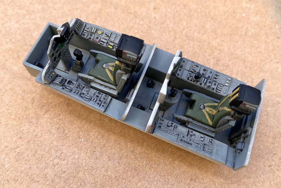
The pilot's seat had parachute risers added, using Evergreen strips, as explained below.
-
Finally, this kit requires a fair amount of weight added to the nose, to sit appropriately. This is appropriately indicated in the instructions sheet. To avoid problems, I basically filled the entire available radome with 5c coins and line sinkers, all cemented with cyanoacrylate.
Notes and lessons learned
I found this kit quite enjoyable. For a budget price, you get a no-frills, reasonably correctly shaped Tornado, with potential to add improvements if you wish to do so. The panel lines are recessed, the fit between parts is OK (nothing that can't be fixed with standard filler and sanding...), and there is no flash worth mentioning.
The amount of weathering suffered by planes during the first Gulf War represents a double-edged sword for the modeller. In one hand, it is quite liberating. The paint tended to erode quickly, and the ground crews sometimes had to touch up with what they had, so most planes ended up with a mishmash of "desert pink" (ARTF - Alkali Removable Temporary Finish), sand, and light brownish colours (e.g. Leyland's "eggshell"). This means that small fixes with the paintbrush, and small variations in colour, look acceptable in the model. On the other hand, the amount of weathering was truly off the scale, creating the expectation that your plane will look very bleached in some parts, and very sooty in others (see below, from the Imperial War Museum collection). It is very easy to overdo this, and end up with something that looks nothing like a real Tornado.
Image credit: the Imperial War Museum
After experimenting with several paints, I used AK desert sand (RC032) as the main colour. To add some variation I used very diluted layers of AK British desert pink (RC043), Tamiya XF-59 (desert yellow) and Tamiya XF-57 (buff), in irregular patterns. I used any of the above colours for paintbrush touch-ups when necessary. I am happy that the colour of the model look at least plausible (i.e. within the variation you see in the contemporary photos). A final layer of Vallejo flat varnish completed the painting.
I chose to under-do the weathering, rather than risk overdoing it. I think it looks suitably grubby, but it could be argued that more soot and dirt would be justified. Well, I tell myself that it was early in the deployment.
As in previous builds, panel lines were reinforced by running a lead pacer over them, and then removing the excess with an eraser run in the direction of the airflow (which can be used to create some interesting effects).
This kit presents no serious problems, but there is some room for improvement...
-
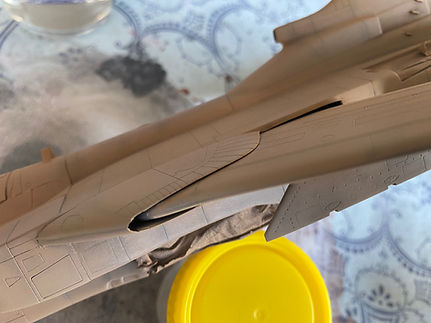
A weak point was a huge gap where the leading edge of the wing meets the wing root. I tried to fix this with filler. The result was far from perfect (yellow arrow in the photo below), but still better than the original.
Left: the original wing root leading edge, with a nasty, unnatural-looking gap.
Right: my fixes" to the wing roots. Red arrow points to the added pneumatic seals, yellow arrow to the reshaped wing root.
-
One of the least satisfactory aspects of this kit is the (lack of) representation of the wing root pneumatic seals. This was just not good enough, which prompted me to scratch build something using evergreen strips (red arrow in the photo above). While not perfect, I still think it is way better than what comes in the box (see here for comparison).
-
The fins in the drop tanks did not match my reference images, requiring some minor surgery to fix their angle.
-
The price one had to pay for adding the pneumatic seals is that the wings are now permanently fixed in the extended position. However, this was not a problem for me. By the time the seals were added (pretty much the last thing), I had already decided that keeping the wings and tailerons movable was just too much trouble. Despite Italeri's best intentions, the mechanisms that allow movement of these parts are too fragile. Moreover, the recommended mode of attachment for the underwing ordnance points (by "hot riveting" them inside the wings) means that they end up very "loose" throughout the build. This made difficult to align the fuel tanks, Sky Shadow ECM pod and BOZ-107 chaff/ flare dispenser.
-
The attachments for the undercarriage leg struts were weak, and kept losing alignment even after allowing plenty of time for the cement to dry. In the end they were all drilled, reinforced with copper wire, and glued with cyanoacrylate, as done for the Privateer. The 4 Mk13 1,000-lb bombs under the fuselage also required some reinforcement for attachment, as there were not guiding pins or holes to help cementing them.
-
The decals are very good, being sharply printed, and just thick enough to make them fully opaque. Unlike in my builds of Italeri's Tigercat and Tomcat, this time most decals were the right size, and matched the instructions. However, just to keep the tradition, Italeri made the stencils in the Sidewinders far too large. I did my best to circumvent this by cutting and splicing these decals, to make more or less fit the length of the missiles.
Click on a picture in the gallery above to see a full resolution image, or to navigate manually


Italeri 1/48 Tornado GR.1 "Armoured Charmer"
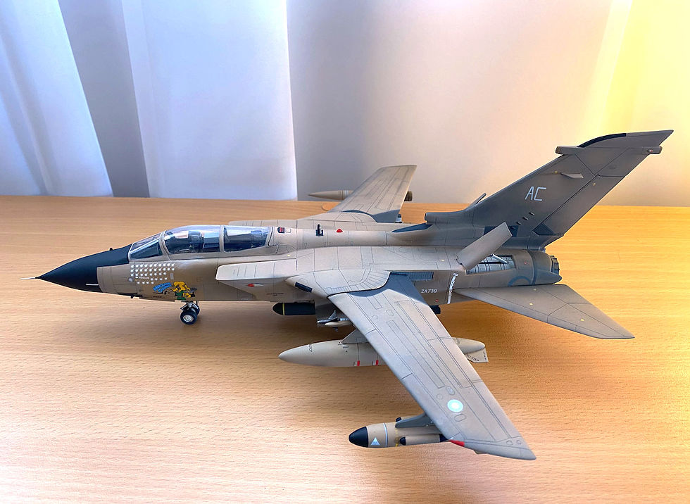
Italeri 1/48 Tornado GR.1 "Armoured Charmer"
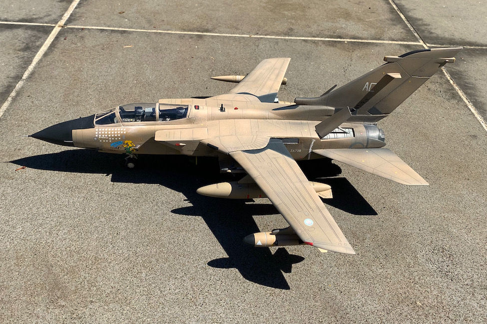
Italeri 1/48 Tornado GR.1 "Armoured Charmer"

Italeri 1/48 Tornado GR.1 "Armoured Charmer"
Construction steps

Construction of the Italeri 1/48 Tornado GR.1

Construction of the Italeri 1/48 Tornado GR.1

Construction of the Italeri 1/48 Tornado GR.1

Construction of the Italeri 1/48 Tornado GR.1
Click on a picture in the gallery above to see a full resolution image, or to navigate manually
-
Font fuselage halves joined, cockpit interior masked. The ejection seats are not cemented at this stage. A layer of Alclad black base and microfiller has been applied.
-
Bottom view of the same stage, showing the nose wheel bay (painted prior to cementing).
-
Main wheel bay fitted. Some internal detail was added using hobby wire and evergreen strips, based on several "walk around" images found in the internet.
-
Dry fitting the top and bottom fuselage, showing the original kit's shape of the swing wing "slot". It is quite different from the one in real Tornado, enough to demand some scratch building.
-
Detail of the reshaped swing wing slot (cut into a rectangular shape, as in the real Tornados). At this stage I still don't know how I'm going to fill this hole with something that looks like wing root pneumatic seals.
-
The internal workings of the swing wing and tailerons, prior to the fuselage being closed. Sadly, in the end these were all fixed on one position. There was just no way I could find to preserve the movement, if the model was to look anything like the real plane...
-
Front view of the main fuselage assembly as it was being cemented. The swing wing mechanism is visible. The kit provides some useful "spacers" (the vertical plastic bits you see near the front) to ensure that this will match to the cockpit and nose assembly with minimal pain.
-
Fuselage, tailplane and dorsal spine tail fairing joined. A significant amount of Vallejo putty was needed to fill gaps between these parts. Apparent is the amount of sanding needed to smooth out the gaps between parts near the swing wing slots, which basically brought back the original plastic colour.
-
After another layer of Alclad primer and microfiller, the fit issues are no longer apparent. The jet nozzles have been painted, weathered, cemented in place (requiring more use of putty to bridge a gap between them and the tail fairing), and masked.
-
The last major job is to join the jet intakes and nose cone. Of course, this means another round of filling, sanding and scribing. This image emphasises which parts were stripped bare in order to make smooth transitions.
-
A ventral view of the same stage. The interiors of the intakes were painted prior to cementing to the fuselage, and appear here masked.
-
More Alclad, and something that looks like a Tornado starts to emerge.
-
After at the first few layers of AK desert sand. Up to this stage the cockpit was still masked. Now, time to fit the ejection seats and canopy.
-
"Middle shading" with Tamiya weathering master (soot and snow), and running a pacer over each panel line.
-
After a few more layers of paint, the weathering is blending more naturally.
-
A ventral view of the same stage as 15.
-
After things were already looking promising, I decided that the gap between the leading edge of the wing and the wing root was not just good enough, and had to be smoothed over with filler. This resulted in another cycle of shading and painting. Now, finally ready for a layer of floor polish, and decals.



Click on a picture in the gallery above to see a full resolution image, or to navigate manually
The Tornado GR.1 cockpit
These images give you some idea of what type of detail you get in this kit's cockpit, pretty much out of the box. The model comes with fair representations of the Martin-Baker Mk.10As, instrument panels and side consoles, but admittedly these are a lot more "schematic" than the ones you can get aftermarket. The only addition to my build were the parachute risers (the vertical belt-like straps in front of the head rests), made from Evergreen strips.
The photos here show the cockpit following painting, sealing with floor polish, and treatment with Tamiya panel accent black. Before closing the fuselage everything got a layer of Vallejo flat varnish (after which the screens were made shiny again with a drop of floor polish). In these images the seats are just dry fitted. In reality they were left out until it was time to close the canopy, to facilitate masking.