 |  |  |  |  |  |
|---|---|---|---|---|---|
 |  |  |  |  |  |
 |  |  |  |  |  |
 |  |  |  |  |
Click on a picture in the gallery above to see a full resolution image, or to navigate manually
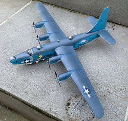
Consolidated PB4Y-2 Privateer
VPB-106, Palawan, Phillipines
May 1945
Why this plane?
I decided to build a PB4Y-2 after accidentally stumbling on the San Diego Air and Space Museum's Image Collection, which has a huge number of digitised photos of the patrol bomber squadrons operating in the Pacific, including VPB-106. This image collection is a fantastic window to an aspect of World War II that is not well publicised, but worth remembering.
To me, the PB4Y-2 Privateer evokes the same reactions as the present day A-10: the aesthetics are best described as controversial, but it surely looks like it means business. Having said that, the PB4Y-2 manages to be a little bit better-looking than its older brother, the B-24 Liberator. After operating modified B-24s in antisubmarine and anti ship interdiction roles (as the PB4Y-1), the US Navy commissioned a fully navalised version. This involved visible differences such as a longer fuselage (to accommodate an extra crew member), a single large vertical stabiliser (for better performance at low altitudes), different engine cowlings (no need for superchargers) and the signature "blisters" (aka Erco tear drop turrets) on the sides of the rear fuselage. I think these changes made the PB4Y-2 look a bit more elegant, at least in flight (nothing can help either the Liberator or the Privateer look graceful on the ground).
What was added (or changed)
No purchased upgrades here. This was an out-of-the-box build. The few additions were all home-made.
-
The kit came with very faint, raised, and generally incorrect panel lines. They disappeared very early in this troubled build (see below), so the solution was to scribe (and re-scribe, sometimes multiple times...) everything. To guide, I used a diagram found in the-blueprints.com (this is a great web site, in case you haven't come across it yet).
-
The twin turret pointing back from the tail was one of the many parts with atrocious fitting issues. In this case, the transition between the clear and opaque parts looked terrible, no matter what I tried, with gaps and/ or steps due to misalignment. My remedy was to add a frame lining the junctions, using very fine evergreen strips (see step 3 below, in "Construction photos"). The actual turret has a riveted frame around the plexiglass, so I think it is OK. It certainly helped smooth the transitions.
-
The aerials sticking obliquely portside, just in front of the wings, were an addition based on the blueprint. They were made from my stash of tungsten wire (see the HMS Eagle page for details). The cables linking the dorsal fuselage to the vertical stabiliser were made from human hair.
-
Ventral recognition lights were created using the same trick I used in the Tigercat build: little drops of Micro Krystal Klear painted, once fully dry, with clear green, red and yellow acrylics.
-
The .50 cal machine gun barrels that come in the kit were way too thick for the scale, and broke constantly. They were substituted with sawn-off hypodermic needles glued with cyanoacrylate.
Notes and lessons learned...
This was one of these kits that fights you every_step_of_the_way. Perhaps not unexpected, considering its age, but I was a bit surprised, since my childhood memories were that Matchbox kits were much more pleasant than others. One way or another, I grossly underestimated the number and extent of problems that I was going to encounter, so what was planned as a quick build took a long time. If I had a "shelf of doom" this model would probably languish there.
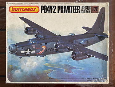
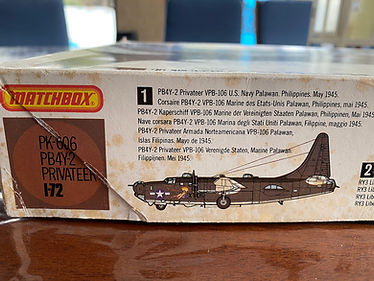
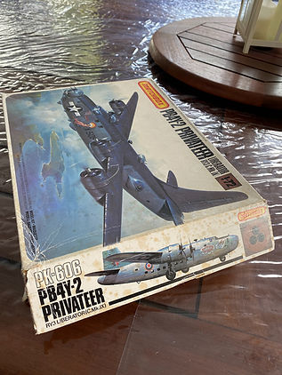
Still, I really wanted to build a Privateer, the idea of converting a B-24 kit was just too daunting, and I found it for a bargain in eBay (currently these kits are going for more than $200 AUD - more than 3 times my investment...). As far as I can determine from the box, this kit was from the original, 1980 release. The box showed weathering compatible with 40+ years:
The sad state of the box. Still, all parts could be accounted for, and nothing was broken.
Problems experienced and circumvented
I start with a list of the problems experienced, and some of the solutions I used. I don't want to sound too negative: It is a great looking model, well worth the effort. This should be seen only as an attempt to save some trouble, in case you decide to build this kit (either in the original Matchbox incarnation or in the more recent Revell; they share the same plastic parts).
-
One general challenge was that the plastic did not play well with Tamiya cement. Seams that I believed had been well cemented together came loose again - sometimes days later, after all the careful sanding, re-scribing and painting had been done. I note that this problem was also experienced by this modeller, who used a different adhesive. Avoiding a visible longitudinal seam between the two halves of the fuselage was a particularly frustrating issue, given the rough handling required to fit the wings (see photo below). This led me to use cyanoacrylate for parts I knew were going to be under strain, like the undercarriage. Still, I wonder what this model will look like in a few years, given the risk that other things will come apart.
-
Fit issues were everywhere. Basically every step involved shaving plastic, lots of sanding, or filling. A prime example was how badly the engine nacelles fitted with the wing, requiring bridging the gap with putty (followed by another dose of sanding and re-scribing...).
The yellow arrows point to visible seams, which had to be dealt with after the fuselage had already been painted, due to the cement not "holding". The light blue is the original colour of the plastic, which resurfaced due to the need to sand. The red arrows point to the ring of Vallejo putty needed to join the engine nacelles to the wings.
-
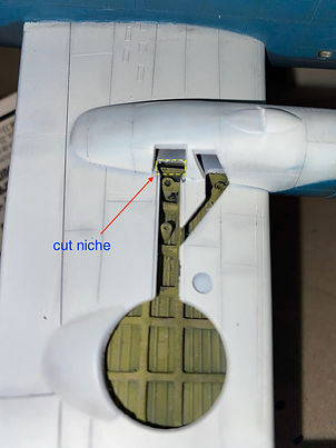
There is simply no way the assembled main undercarriage can fit in the slot provided: the wheel covers hit the wing surface before the main strut "pin" can fit into the wing "hole". My solution, shown below, was to cut a niche on the wing surface, just wide enough to make the main wheel assemblies slide into place. By the way, I echo the view that the internal detail of the wheel bays is exaggerated. What you see in the images below follows a lot of shaving and sanding plastic, to make the internal features a bit more "natural" - as in, it looks like the wheels could actually retract.
-
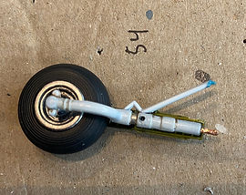
The plastic pins supposed to fix the wheel struts to the airframe did not look like they would cope with the amount of nose weight needed (see step 5 of the Construction photos). I ended up also cutting them off and substituting with sturdy, thick copper wire fixed into holes drilled into the struts. In the case of the front wheel, this was additionally important, as the pin in the original part was very short, leading to instability. A longer piece of copper and the use of cyanoacrylate helped.
Customisation of the undercarriage - nose wheel (left) and one of the main wheels (right).
-
The canopy comes in 3 pieces. For some reason the piece that covers the starboard side fitted in the gap like a dream, but the port side didn't fit at all. While doing a lot of shaving and sanding I took the opportunity to cut it so as to represent the pilot's "bubble" window slid backwards, as sometimes done on the ground (see also here). Given how thick the canopy clear plastic is, and its relatively heavy frame, peering through this window is the only way to see some of the cockpit's insides.
The real "Redwing" (BuNO 59505) with the pilot's window open. Image source: ARC forums
-
My biggest problem, which I confess was partially self-inflicted, was attaching the wings to the fuselage. The assembled wings have to fit into elongated slots (see step 2 in the Construction photos below). This is a rather physical process, requiring some rough handling. Still, with enough pushing and shoving the port side wing clicks in like a dream, and stays firm at a reassuringly correct angle. The starboard side...well, no matter how much I tried it, just could not do the same. This modeller reported the same experience, so it must be some basic issue with the mold. Anyway, a lot of plastic shaving and sanding later, I managed to get it in; but, critically, at this point I just eyeballed to conclude "yeah, the angle looks right", and proceeded to fill gaps, paint, etc. until the model was ready for decals. It was not until the undercarriage was installed that I found, much to my horror, that the starboard side wing was sitting at a slight dihedral angle; given the long wings, this resulted in the fuselage being visibly not vertical. What came after that was a comedy of errors, which ultimately required breaking off the starboard wing, and re-doing everything. In the process I managed to create a visible depression on the dorsal wing surface, which had to be filled with Vallejo putty, sanded multiple times, re-scribed, etc. This added a month to the build. Anyway the point is: this step is tricky; check carefully if the wings are symmetrical.
-
The engines are not detailed. The instructions would have you place parts that look like two rings linked by a dense array of spokes (parts 61) in front of the engines. I suppose these are meant to represent the spark plug leads (?). The problem is that these look like nothing in the real plane, and obscure everything else. I opted to cut the outer ring and "leads", and to use the inner ring basically as a spacer so the propellers stay at the right distance. See step 3 of the Construction photos for a view of what the engines ended up looking like.
-
The kit allows you to build one of 3 versions of the Privateer, and they each have a different combination of windows. This means that you are supposed to cut off rectangular bits of plastic from the sides of the fuselage, and then fit clear parts in different places, depending on the choice. This is not particularly easy to do, and my results were mixed. In any case, this is one place where the instructions were incorrect: they omit the fourth portside window, just ahead of the wing and bomb bay doors (see here).
-
Finally: there has been some discussion in internet forums about how the engine cowlings in this model are wrong, and most of the articles I found recommend getting aftermarket resin replacements. I must say that what came in the box did not bother me at all, and looked pretty close to the correct shape. The propellers, on the other hand, did look terrible. I did my best to get them somewhat closer to the truth by carefully sanding each blade.
...a few more pictures...
Click on a picture in the gallery above to see a full resolution image, or to navigate manually
...some positive lessons and observations...
-
Predictably, the decals were in a sad state: the decal sheet was warped, and everything was yellowed. There was also a sheet of flimsy paper stuck to the front surface, that had to be pried off carefully, but left some residue. Given how hard (and expensive) it would be to find aftermarket decal sets for this old model, this was a constant worry during the construction. Yet, I found there was nothing to worry about. Following the recommendation of some YouTube videos (like this one) I placed the decal sheet in a place where it would be exposed to direct sunlight every day, from day 1. Miraculously, over the following weeks, this led to it gradually straightening, losing the yellow tone, and even dropping the paper residue (upon gentle brushing). I still worried about the decals breaking into pieces, and prepared for this possibility by scanning the decal sheet at ultra high resolution (which I will be happy to share with anyone; low resolution version here). Yet, they performed like new.
-
My fine airbrushing skills are not good enough to do pre-shading, particularly in 1/72 scale, and just using post-shading can lead to unrealistic results (at least, in my hands). In an attempt to circumvent these limitations, I improvised a "middle shading" technique - not sure if the name really exists. I will illustrate this using photos of the ventral surfaces of the PB4Y-2.
-
I started with a uniform (but not too thick) layer of SMS insignia white (FS17875) airbrushed on top of Alclad glossy black base primer.
-
Next step, I used various tones of Tamiya weathering master (e.g. oil stain, soot, rust, burned blue) to highlight the vicinity of panel lines, and to add some heterogeneity. This photo shows the model at the end of this step.
3. Panel lines were also accentuated by running a fine pacer along them (see Tomcat build).
4. Finally, several thin layers of insignia white, until the unnaturally sharp transitions faded.
The end result is what you see in the galleries. After masking the white, I did the same for the light blue colour that covers the side surfaces of the plane, and finally the dark sea blue (top surfaces). I found this suitable for my purposes, and a lot easier to control in order to achieve not-too-obvious variations in surface colour (including panel lines). One of the advantages of this approach is that, if you over-do the painting, you can always add another layer weathering master accents (even to a specific region), and just airbrush again.
-
As a last note: I found really hard to find sources for the blue colour that should go on the sides of this plane. The instructions suggested Humbrol RAF blue, which looked too dark, and the only colour photos I could find are from restored planes, such as these in the Pima Air and Space Museum and the Naval Aviation Museum in Pensacola. I trusted that the museum curators know their business, and mixed paints until the desired effect was reached. The final mix was about equal parts of Tamiya X-14 (sky blue) and XF-18 (flat medium blue). To my eyes it looks "right" under indoors illumination (see gallery below).
...and a few more photos
In conclusion: I got my PB4Y-2, and is a great looking model even thought my execution was not perfect in many ways. There are lots of things that I would do differently if given another chance, but this kit (or, any other Privateer kit, for the matter) has been out of production for a long time. I am glad I have had a chance to build one.




Construction photos
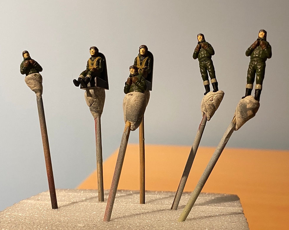
The 1/72 crew member figures in the Matchbox PB4Y-2 privateer

The half-fuselage of Matchbox's PB4Y-2 Privateer, following inserting the view ports and scribing panel lines.
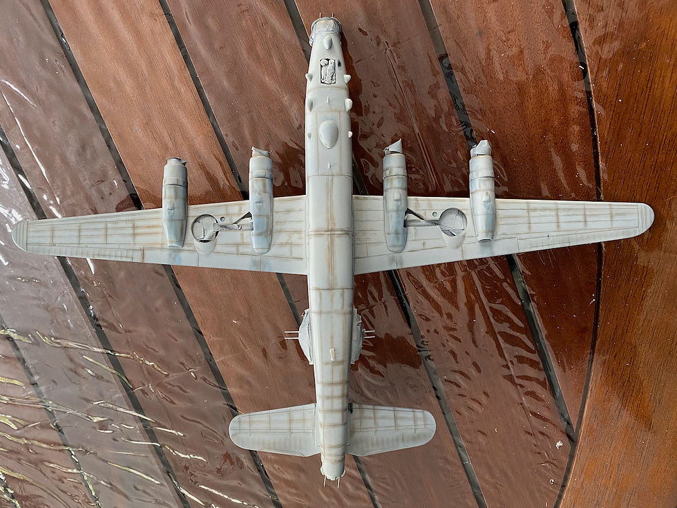
After a first layer of insignia white, some pre-shading (or middle shading?) with Tamiya Weathering Master.

The 1/72 crew member figures in the Matchbox PB4Y-2 privateer
Click on a picture in the gallery above to see a full resolution image, or to navigate manually
1. Step 1: Meet the crew.
2. After several days of work, the windows are added, and made flush with the fuselage. This was a really fiddly job. Given the amount of sanding needed, I decided to be proactive and scribe recessed panel lines.
3. A lot of time is needed to build the turrets. Joining the pieces to make the nose turret (Erco Ball turret) and the tail turret (Consolidated MPC250CH-6) would be easy if you had 3 hands, but for me this required a lot of attempts involving dropping pieces on the floor. For the engines, I decided to ignore the instructions and not use the mysterious plastic rings (parts 61). These do not seem to correspond to any part of the real Twin Wasp R-1830-94 engines, and, if used, completely obscure the cylinder mounts.
4. Cockpit assembled. This is what you get out of the box. I could have spiced it up but it soon became clear that this will be barely visible after the canopy is added. Sorry about that.
5. Prior to joining the fuselage; the side blisters (aka Erco Tear drop turrets) are glued in and joined, requiring a lot of fine filling and sanding to avoid gaps). This image shows how much weight I put in the front. I hope this will be enough...
6. Fuselage halves joined, nose section added. By that stage I have already had a go at painting the fuselage (Alclad black base, followed by the mixed acrylics I explain above) to test whether the colour would look good. But then, a lot of sanding was required to make the joint between nose and main sections of the fuselage, and between the fuselage halves, smooth. At this stage, the vertical and horizontal stabilisers had also been added, and joints filled with Vallejo putty.
7. Both wings glued, sanded, and scribed. Not shown here, the wheel wells (masked here in preparation for painting) were painted interior (zinc chromate) green before the half-wings were joined. At this stage, the engine nacelles are just dry-fitted.
8. Finally taking shape. Clear parts masked in preparation for painting. Note the amount of white putty needed following joining the engine nacelles to the wings.
9. After an initial layer of insignia white (SMS), I applied some shading using Tamiya Weathering Master (oil stain, burnt blue and rust in different places). It looks pretty bad at the moment, but the effect will becomes subtler as additional fine layers of white lacquer are applied on top.


