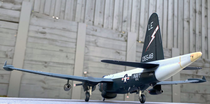
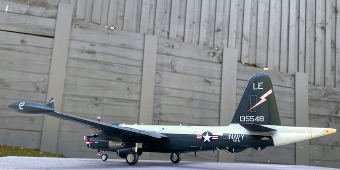
 |  |  |  |  |  | 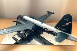 |
|---|---|---|---|---|---|---|
 |  |  |  |  |  |  |
 |  |  |  |  |  |  |
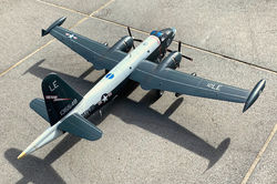 |  |  |  |  | 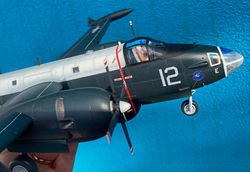 |  |
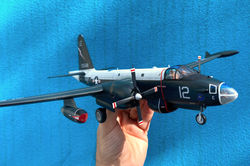 |  | 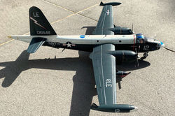 |  |  |  |  |
 |  |
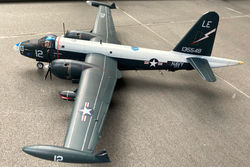
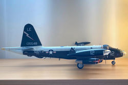
Click on a picture in the gallery above to see a full resolution image, or to navigate manually
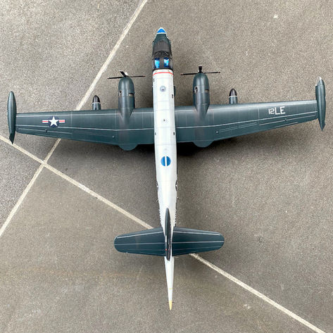
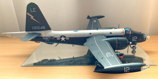
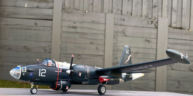
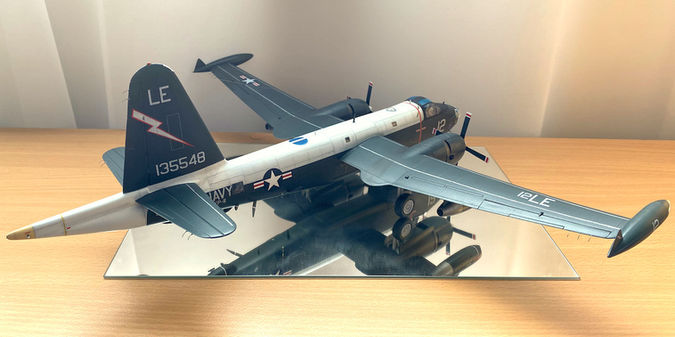
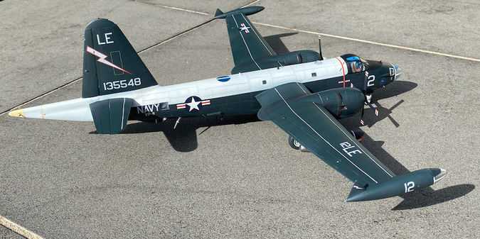
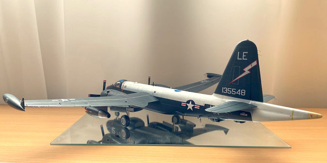
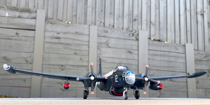
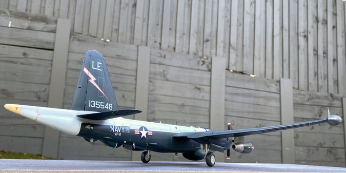
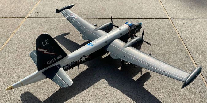
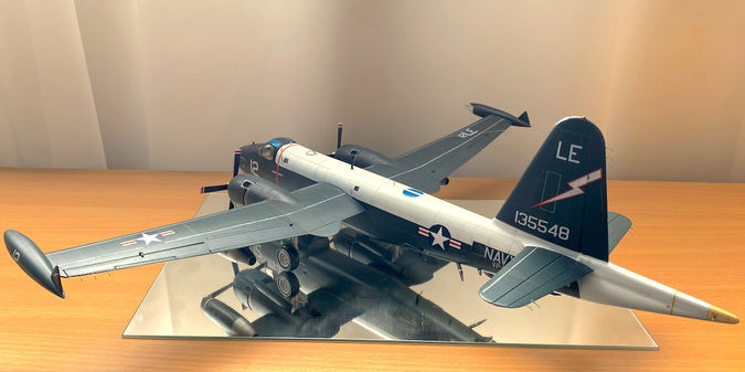
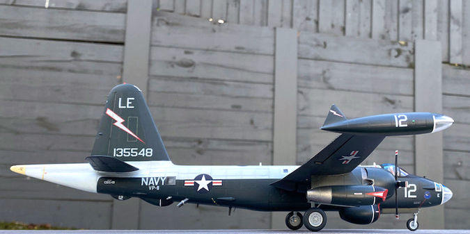
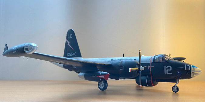
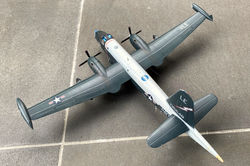
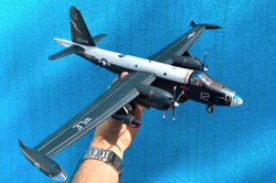
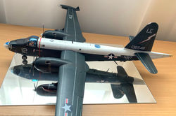
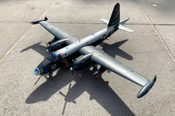
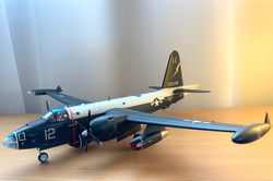
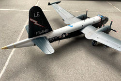
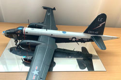
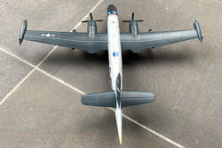
Lockheed P2V-7 (SP-2H) Neptune
VP-11, Keflavik, Iceland
June 1963
Why this plane?
Neptunes used to be frequent sights over the beaches of Salvador, Bahia, where I lived for a few years as a kid. I am old enough to remember one of the last Neptunes in service with the Brazilian Air Force shaking every window of my house during a low flyby. The combination of huge radial and jet engines was loud, and you can imagine the impression this made.
A nice painting of a Brazilian P2V-5 as I remember them. From the Brazilian Air Force Aerospace Museum, Rio de Janeiro. Shared by Luis Ferreira at https://www.flickr.com/photos/luigibrasile/2093749224
Neptunes also had a feature that represented to me (as a young boy) the best workplace anyone could have: the observer seat, which could be moved forward so as to overhang the perspex nose, separated from the world only by a metal foot support (some good photos here and here).
What was added (or changed)
-
The nice person who sold this kit on eBay surprised me by including the Eduard interior detail photoetch sheet in the package, and I could not refuse using it. This proved a mixed blessing; it makes the model look a little bit nicer, but requires a lot of additional work, as it does not really fit well with the plastic (details below).
-
As expected from a kit from the 1980's the decals were yellowed. I tried the same trick that worked wonders in the PB4Y-2 Privateer (prolonged exposure to sunlight). The yellowness did disappear after a month, but test runs showed that the decals had became incredibly brittle, breaking into many pieces at any attempt to drag them into position. At this point I decided to pay for an aftermarket set from Printscale, which proved to have their own problems (see below).
Other additions were home-made, including:
-
Panel lines were scribed on top of the original raised ones.
-
The metal "cage" under the observer's station was built from hobby wire, to substitute the rudimentary part included in the kit.
Observer's station:
Top left: Front view of a Neptune, showing the metal "cage" that serves as foot support for the observer. Image credit: www.net-maquettes.com. Top right: Part 51 in the kit, which was supposed to represent the "cage". Not good enough! Middle: the replacement built from hobby wire. Bottom: following installation of the clear part that represents the Perspex "nose".
-
The aerial running from the astrodome to the vertical stabiliser was made from human hair.
-
As you may imagine just looking the pictures, this kit demands a lot of ballast towards the front end, to avoid becoming a tail-sitter. How much, however, surprised me...see below.
Notes and lessons learned...
This is an old kit, but it gives you an accurately shaped model of a Neptune straight out of the box. The panel lines are all raised, there is no detail whatsoever in the wheel bays, and the cockpit is pretty basic.
The fitting of parts is OK (but not great), with only a few tricky points.
-
The alignment of the wings can cause problems if you are not paying attention. The images below tell the story. The two wing assemblies each have 3 tabs, which are supposed to be complementary and alternate inside the fuselage, creating a solid lock. Sounds good in theory, but dry fitting showed that this results in wings that are not symmetrical relative to the fuselage and horizontal stabilisers. My solution was to shorten the tabs so they don't interlock, and making sure the wings meet the fuselage at square angles before cementing them in place.
Aligning the wings:
Top left: front view of the two wing assemblies illustrating the interlocking tabs, which are supposed to alternate inside the fuselage. Top right: dry fitting the wings to the fuselage assembly reveals that this mechanism results in wings at different angles from the fuselage. Bottom: following shortening of the tabs, the wings can be cemented at a straight angles relative to the fuselage.
-
Another problem came from the decision to use the Eduard internal detail set, while attempting to preserve the Hasegawa crew figures and seats. The crew, as provided, has the legs extended in a way that does not align with the pedals, and they hit the instrument panel provided in the photoetch set. Luckily I test-fitted using white glue, before going to cyanoacrylate. The solution was to perform knee surgery in the pilot and co-pilot, as shown in the pictures below. In addition to this problem, the side instrument panels were too wide to fit between the seats the fuselage walls, requiring some photoetched metal to be trimmed. It looks weird in the pictures below, but this is not noticeable once the canopy is in place.
Cockpit:
Top left: The pilot with the legs in the original extended position, with feet in the air. The co-pilot legs had been cut, with the left one reattached in a flexed position. The seat belts are from the Eduard photoetch. Top right: legs reattached. Left: after the successful knee surgeries and some Vallejo putty. Bottom: two views of the cockpit showing how the side instrument panels had to be trimmed in order to fit between the seats and fuselage walls.
-
Getting the propellers "right" demands patience. In part because painting them requires a lot of successive masking, but mainly because each blade comes separately, and you need to attach them one by one. This involves making sure, first, that they are at right angles from each other, and second, that they have the same pitch.
Propellers:
Left: Making each propeller requires cementing 6 parts. In this picture the 2 parts making each hub are already joined. Each propeller blade was painted separately (first black, then blue, then white, then red, masking progressively after each step). Right: Each blade has to be attached separately. Keeping them at 90˚ from each other AND with the same pitch is a test of patience, best done by using slow setting cement (so you have plenty of time for tweaks), and waiting until one is rock solid before proceeding to the next.
-
This model requires a lot of nose weight to keep the tail off the ground. As shown below, I initially thought filling the radar dome with metal would be enough. This proved to be far from the case. Having already closed the fuselage at that stage, the solution was to fill any other empty space in front of the main undercarriage with line sinkers. This included the front part of the jet pods and wingtip fuel tanks, as well as a small space between the engines and the nacelle firewall. This was just enough to avoid a tail-sitter.
Preventing a tail sitter:
Top left: Half fuselages showing the radar dome filled with metal. This was not enough...making me scramble for other places to fill with weight. Top right: Each jet engine could take 3 line sinkers. Not shown here, the wingtip fuel tanks also each got 2. Bottom: the spaces (indicated by arrows) between the engines and nacelle walls, which also got filled with line sinkers.
-
As mentioned, this build required aftermarket decals. Not to put too fine a point on it, they were disappointing both in terms of accuracy and quality. For example, to appropriately model the plane I chose to reproduce (BuNo 135548 as part of VP-11, 1963), the following had to be sourced from the spares box, or home printed:
-
The letters 12LE on the right wing;
-
The white "walkway" stripes on top of the wings and horizontal stabilisers (here the solution was to carefully piece together the fragments of old Hasegawa decal...);
-
The "Danger- jet intake" stencils on the inner surfaces of the jet engine (the decal sheet only provided decals for the outer surfaces);
-
A number of white lines, for example around the jet engine pods and AN-APA-69 direction finder antenna.
-
-
In other cases, decals were provided, but with no allowance for the fact that sometimes left- and right-hand side versions are needed. On this account, the "rescue" arrows ended up upside down on the right side...
-
Finally, the decals were so thin that it became a very visible problem when they straddled the blue and white surfaces (in particular, the fuselage "star and stripes"; see below). The solution was to remove and substitute with some leftover Cartograf decals, from the spares box.
Trouble with Printscale decals:
Top left: No decals were provided for the inner surfaces of the jet pods, so they had to be made from bits and pieces. This image shows an "in progress" stage. The white decal triangle was subsequently overlaid with a red "danger- jet intake" stripe from the spares. Top right: The "rescue" arrows were all the same, so they ended up upside down on the right side. Bottom: Thin decals meant that the boundary between white and blue was visible under the star.
...and few more pictures...
Click on a picture to see a full resolution image, or to navigate manually


.jpeg)


Patrol bombers!

1/72 models representing two generations of US Navy patrol bombers: PB4Y-2 Privateer (Matchbox) and P2V-7 Neptune (Hasegawa).

1/72 models representing two generations of US Navy patrol bombers: PB4Y-2 Privateer (Matchbox) and P2V-7 Neptune (Hasegawa).
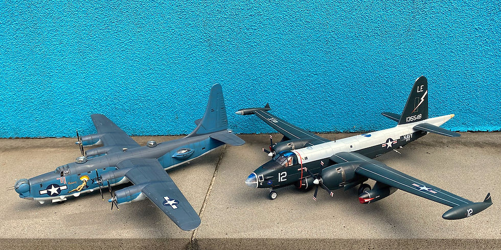
1/72 models representing two generations of US Navy patrol bombers: PB4Y-2 Privateer (Matchbox) and P2V-7 Neptune (Hasegawa).

1/72 models representing two generations of US Navy patrol bombers: PB4Y-2 Privateer (Matchbox) and P2V-7 Neptune (Hasegawa).
Click on a picture in the gallery above to see a full resolution image, or to navigate manually
Two generations of USN patrol bombers, side by side, in 1/72 scale: the PB4Y-2 Privateer, and the P2V-7 Neptune.
One thing that surprised me is how large the Neptune is, being comparable to a World War II bomber (the Privateer being a stretched version of the B-24 Liberator). I think the impression of a smaller airframe comes from in part from the much larger canopy and engines.
Perhaps also noticeable is the fact that the weathering in the Neptune model is much lighter, in my attempt to reflect the realities of prolonged wartime duty vs. peacetime operations.
