 | _at_anchor_in_the_Firth_of_Clyde,_Scotland_(UK),_during_NATO_Operation_Mainbrace,_in_September_1952_(80-G-K-12832).jpg) |  |  |
|---|---|---|---|
 |  |  |  |
 |  |  |  |
 |  |  |  |
 |  |  |  |
 |  |  |  |
 |  |  |  |
 |  |  |  |
 |  |  |
Click on a picture in the gallery above to see a full resolution image, or to navigate manually. For more images, scroll down
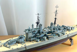
HMS Vanguard
North Atlantic,1946
Why this ship?
Vanguard was not only the Royal Navy’s last battleship, but also the last battleship to be commissioned anywhere in the world. And also, in my view, and extremely good looking ship. I decided a long time ago that she would be an excellent subject for model making. What I didn't realise at the time was that is not an easy proposition.
There aren't many options from kit manufacturers. In fact, when I started this project, the only option available was a Haseagawa/Frog kit, originally from 1969, and in an odd scale (1/450). Based on the box art, my kit was from a 1980 re-release. In the box there was a little electric motor, which was supposed to be connected to a single a plastic propeller through a hole at the bottom of the hull.
Even after reading all negative reviews online, I was not prepared for how primitive this kit is. It has a grand total of 70 different parts (145 in total, accounting for multiple copies of items such as gun barrels). There was zero detail. For example, the superstructure parts were like Lego blocks with no portholes, raised or engraved detail - except that, unlike Lego blocks, they did not align with each other. There are some example pictures below.
As evident from the list of modifications I did (see below), what started as a “let’s improve it a bit” escalated into a major exercise of “let’s see how much lipstick this pig can take”.
Left: I was fooled by the Box art. Not easy to assemble, no quality detail, parts were far from precise. It is hard to believe that Hasegawa was still re-releasing this kit as recently as 2011! Top right: The total extent of the box contents. Bottom right: Note the nasty seam line along the hull spine. Seam lines are a bane of this kit. There is not a single part that dispenses a lot of sanding.
What was added
In summary: the only original parts that made to the end were the hull, deck, major building blocks of the superstructure, and stacks. Even these were modified, as explained below. For the rest, you can assume it was either 3D printed, part of a photoetch upgrade, or scratch built.
Fortunately there are many good surviving photos of Vanguard, some of which I attach here at the end of this folder. Also fantastic were the schematics in the “TopDrawings” book (still the best reference for this ship, which my local library managed to borrow from somewhere in Poland).
In no particular order, and probably forgetting something:
-
Wooden deck from Artworx;
-
All hull plating scribed by hand. The sides above the waterline are I believe pretty accurate, based on photos of Vanguard, but under the waterline it is a mostly a guess, based on photos of other battleships (like this one).
One of the images used for referencing the hull plating. Image credit: https://www.destinationsjourney.com/historical-military-photographs/british-battleship-hms-vanguard/. This web site has one of the best collections of images of Vanguard.
-
A lot of the top level of the bridge had to be scratch-built from Evergreen, as most details were either wrong or absent;
-
The propellers, rudder and propeller guards were heavily reshaped based on the only photo of Vanguard in dry dock that I could find, and the diagrams in the TopDrawings book.
Left: The real shape of Vanguard's rudder. Image credit: https://www.destinationsjourney.com/historical-military-photographs/british-battleship-hms-vanguard/. Right: the kit's version.
-
A photoetch set from Atlantic Models was used for masts, safety nets, ladders, railing, davits, doors, hatches, radars and other antennas, funnel grills, crane jibs and hooks, 20mm Oerlikons, jack and ensign staffs, cable drum ends, bridge rear side platforms, anchors, and anchor chains;
-
Main and secondary turrets, mushroom vents and boats were 3D printed by Micro Master;
-
Single and sextuple 40 mm Bofors mounts 3D printed by DiStefano 3D print. In the single mounts I actually transplanted the barrels from the Atlantic Models set, to replace of the 3D printed ones which appeared over-scaled;
Left: Single mounted Bofors 40 mm guns as provided in the kit. Right: the 3D printed version, with barrel from the Atlantic Models set transplanted, and in original form.
-
Carley floats and Type 262 directors were resin printed by my friend Azrael, as a huge favour;
-
A myriad of ammo boxes, lockers, pipes and other details made from Evergreen, spare photoetch sprue or hobby wire;
-
All portholes and scupper holes were drilled manually. The portlights were simulated with drops of white glue (Micro Krystal Klear);
-
Rigging was done with a combination of Uschi elastic thread and human hair;
-
The twin 40mm STAAG on top of turret B was a mixture of barrels from Atlantic Models and scratch building with Evergreen and leftover bits of photoetch. The platform where this mount sits is provided as part of the Micro Master set;
-
The square windows on the bridge and Vanguard crest are home printed decals;
-
The quarter deck DF antenna and its stand were a combination of parts from the Atlantic Models set and scratch building;
-
The base of the cranes was scratch built;
-
The 4 “chutes” on the side of the hull, near midships, were created by shaping Evergreen rods;
-
The whip antennas attached to the stacks and on the fore and aft decks were created from tungsten rod.
-
Fore and aft extensions of the armour belt were missing, so these were created with strips of Evergreen sheet.
I will stop here, but essentially every detail was added. And to top this, the fit between the main parts was disgraceful. Some of the worst examples shown below. Every step was accompanied by a lot of sanding and filling…
Left: Starboard view of the main superstructure including the bridge. Right: corresponding port view. No, I am not misaligning the parts on purpose, just for the photo. It is really that bad.
Notes and lessons learned
The main lesson I learned is to avoid such old kits with a lot of bad reviews. Building this kit took 6 months of my life which I could have used to build 2-3 better models. Having said that, if you are interested, here are some notes:
-
Painting above the waterline was done primarily with Tamiya TS-81 (vertical surfaces). To break the monotone a bit, and to add highlights and other touch ups I used Tamiya enamels; either XF-12 (JN grey), or XF-25 (Light sea grey), often diluted to avoid big transitions. The greenish dark grey for horizontal surfaces was XF-22 (RLM grey).
-
Painting below the waterline was primarily with mixtures of XF-7 (red) and XF-9 (hull red). I tried not to be too precise each time I mixed these two, to add some variety.
-
Once I was happy with the painting job, everything was sealed with SMS clear gloss (PL09), and decals and weathering were applied. The decals were from Sovereign Hobbies (RN draught markings 1/400 scale).
-
This was the first time I tried to create suggestion of a scum line as part of the weathering job/ This was done by applying splotches of XF-26 (deep green) and XF-58 (olive green), both well diluted with white spirits, and then spreading the paint with a flat brush dipped in white spirits.
-
The flags were home-printed in a standard laser printer.
And a few more pictures...
Click on a picture in the gallery above to see a full resolution image, or to navigate manually


Construction photos

Steps in the construction of the 1/450 Hasegawa HMS Vanguard

Steps in the construction of the 1/450 Hasegawa HMS Vanguard

Steps in the construction of the 1/450 Hasegawa HMS Vanguard
Steps in the construction of the 1/450 Hasegawa HMS Vanguard
Click on a picture in the gallery above to see a full resolution image, or to navigate manually
1. The initial task was to prepare the hull. This started by filling the hole where the shaft for the electric motor (not used) was supposed to go. As it turns out the shape of the "fin" along the centreline was also wrong, so this had to be built up with Evergreen and filler, to get something a little bit closer to the real thing. Another preparation step was to sand smooth a nasty ridge along the hull's spine.
2. A few days were spent creating hull plating. First drawing with lead pencil, then scribing. Portholes were drilled.
3. The armour belt extensions were not represented by the kit. They were added with Evergreen sheet (black in this photo). This photo from the construction of Hood suggests what these should look like.
4. One of the many inaccuracies of this kit is the fact that the propellers have flat ends. I used the tips of these clean room sticks to create a shape similar to the one in the reference image, and blended using Micro Krystal Klear.
5. A more natural representation of the connection between shafts and the hull was also created with Micro Krystal Klear. Once dry, these additions become transparent, and could be painted over.
6. Micro Krystal Klear was also used to reshape the shaft brackets. Note here that the rudder has also been reshaped.
7. With all the details underneath added, it was time to paint the hull red. Some variation was created by letting Tamiya panel line accent run along the limits of the plates, between coats, and blending these with lighter fluid.
8. Next the red parts of the hull were masked, and the black applied for the boot line. Then masking the boot line, and painting the grey with Tamiya TS-81. This sequence resulted in a nice demarcation.
9. With the hull prepared, it was time to start on the superstructure. As mentioned above, the fitting was atrocious. This image shows the bridge after a lot of sanding to remove the unnatural steps between levels. Note, no portholes or any detail at this stage.
10. This is how misaligned the to halves of the smokestacks were...
11. Also notable are the terrible seam lines created by mould flash, and the awkward locations of the sprue gates. All of this had to be sanded...
12. The representations of the Type 275 fire control units were comically wrong, with a huge "neck" among other inaccuracies (left). To the right, the beginning of my attempt to make these less obvious.
13. With the stacks added and superstructure more or less completed, a next step was to add the platforms for the Bofors sextuple mounts. Here you see the problem: huge gaps that would be nearly impossible to sand smooth. The moulded ladders on the sides of the stacks had bib this stage been sanded smooth, for being in the wrong places. Detail was added in the right places including new photoetch ladders.
14. My solution to deal with the problem of the Bofors platforms was to cut some discs of Evergreen sheet, and apply them on top of the platforms (black). In this photo some other detail is being added, to represent structures that were obvious in the ship diagrams, but not represented at all in the kit (white). These bits of Evergreen ended up everywhere. The oblique "pole" was later removed and substituted with a sawed off hypodermic needle.
15. Time to apply the wooden deck.
16. Before the wooden deck is applied to the forecastle it had to be sanded smooth to create good adhesion. This image shows this job in progress. Note also the structure behind the first wave breaker, with 3 disk-like objects on top. This had to be raised and built to a more accurate shape before the wooden deck was applied. This required some removal of wood planks around it, since the ArtWorks deck is designed to fit precisely the Hasegawa model (and it does a good job of that).
17. There were a lot of vents on the barbettes which had to be scratch built.
18. The kit does not include representations of The type 262 radar units (used for guiding the Bofors guns). Here I relied on a big favour from my friend Azrael, who is a wizard in resin printing. He created these units from a 3D model I found online!
19. Azrael also printed these beautiful Carley floats.
20. Some of the Carley floats in place. Also note the PE safety nets around the sextuple Bofors mounts. Vanguard also had a lot of these "pole" objects scattered everywhere, the function of which I could not find. I added them by cutting and sanding hypodermic needles.
21. The main and secondary armament were ordered from Micro Master. This is how they arrive. I had a lot of fun cutting those supports (NOT!).
22. Then it was time to black prime a lot of resin parts, after cleaning them well with soap and isopropyl alcohol.
23. The next big job was to create the STAAG (Stabilized Tachymetric Anti-Aircraft Gun) twin Bofors on top of the B turret. Here I used barrels from the Atlantic Models photoetch, and created the rest from bits of spare photoetch and Evergreen.
24. Next steps involved adding 3D printed and photo etched details. This was done from inside (i.e. near the ships' centreline) out. Here some of the railings and ladders had already been applied near the centre.
25. Each mast was treated as a separate sub-assembly, to be added at the very end. Here I show some braces that needed to be added to the fore mast assembly, which were not represented by the kit.
26. Before building each mast I attached them in place with wood glue. This allowed me to make adjustments in the length of the individual legs of the tripods, to ensure vertical alignment. Once I was sure each mast would stand straight, they were yanked out and built separately.
27. This shows the main mast sub-assembly being painted. I only attached them with cement after everything was ready.
28. The final steps included the rigging, and adding the outer layer of railing.